Innovation in action: 191 overhead travelling cranes in operation at KraussMaffei
KraussMaffei Technologies GmbH is an international company based in Germany with a long tradition in the plastics processing and mechanical engineering industries. With over 185 years of experience, KraussMaffei has made a name for itself as a reliable partner for challenging projects. The company offers state-of-the-art solutions in injection moulding, reaction processing and automation as well as supplying customers in a wide range of industries, including automotive, packaging, medical and electrical engineering.

The world's leading manufacturer of plastic injection moulding machines, KraussMaffei Technologies GmbH, has ordered a total of 191 crane systems from us, ABUS Kransysteme GmbH, for its new plant in Parsdorf near Munich. The cranes will be used there to support all aspects of the internal flow of materials. The decision was made to use various crane systems from the ABUS product portfolio. In total, 147 overhead travelling cranes and 44 jib cranes and HB light crane systems were ordered.
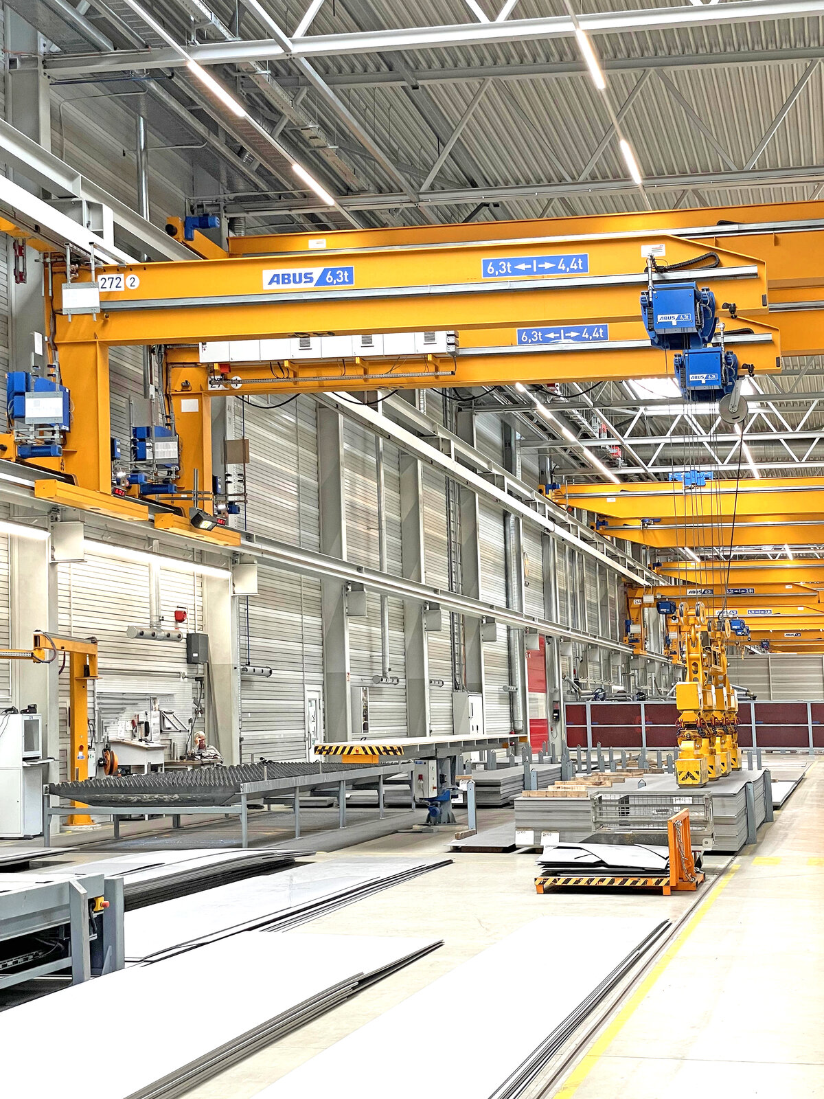
The ABUS cranes will be used in KraussMaffei's new plant for loading and unloading tasks for incoming and outgoing goods, support logistics processes for individual parts and spare parts storage and, above all, enable assembly processes for the machines manufactured at KraussMaffei. The overhead travelling cranes are used to lift individual parts and bring them into position for bolting and assembly onto the machine. Entire assemblies and finished machines are also transported back and forth between the production stations. Cranes with two crab units are particularly helpful for this, as they can be used to lift and move the finished machines evenly at several attachment points. We accompanied one of the cranes, a double girder overhead travelling crane with a span of 22 metres and a load capacity of 80 tonnes, during its construction at our production plant in Gummersbach-Herreshagen and took a step by step look at how an overhead travelling crane is created from steel plates, cables and a rope.
Delivery & preparation of the raw material
The foundation for KraussMaffei's cranes
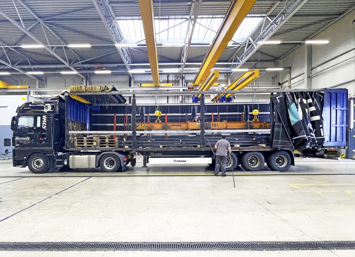
At the start they are normal steel sheets, just 6 mm thick. The pre-cut sheets arrive by lorry at the incoming goods department of the production facilities at the ABUS plant in Gummersbach-Herreshagen. The operatives unload the vehicle and then use a magnetic lifting beam to load the sheets onto the feeder of the shot blasting machine. This is the first step: in this system, the material is blasted, i.e., shot with small, hard steel balls. This loosens rust and impurities and the surface is optimally prepared for further processing. From this point on, the production process is planned in detail and it is already clear that the blasted plates are intended for exactly this one crane at Krauss Maffei. There is no make-to-stock production or stockpiling at this point.
Every overhead travelling crane manufactured at ABUS is commissioned right from the start. Although it is therefore already a one-off, it is also a series product: the entire static calculation, the electrical equipment and everything else that will later be fitted to this crane has already been specified and planned in digital assemblies. In this way, the crane is optimally matched to the customer's requirements, but can still be built efficiently and quickly, and is thus more favourably priced than if a bespoke engineering design had been necessary beforehand. The required metal sheets are now already in the transport bogey on their way to the next step in production.
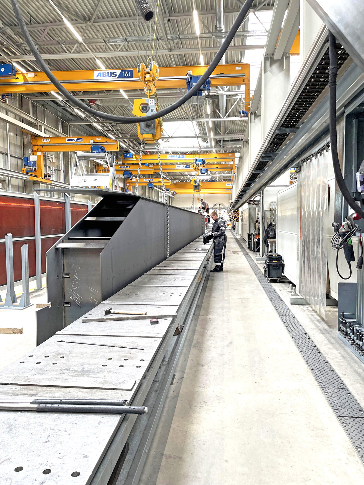
Functional welding
The basis for flawless cranes at KraussMaffei
The next production step involves assembling the crane. The next step is to build a box-shaped beam from the sheet metal, which - with a material thickness of only 5 millimetres - can later lift a load of up to 80 tonnes. To do this, various components are welded on. First, however, the blasted pieces of sheet metal have to be joined together in order to obtain the length of the future box girder. To do this, the sheets are simply placed next to each other and mechanically welded at the ends, i.e. the sheet edges. Later, on the crane, these points can be recognised by vertical seams.
Even at this early stage, the crane girder is given the span dimension determined by the bay width of the new factory at KraussMaffei, as advised by their planning engineers.
The next step is a manual one: the various sheets are lined up in the shape of the future box girder and secured with spot welds. Alongside the long side plates, the web plates, are the upper and lower sides of the box girder, which are called the upper and lower flanges, as well as a few more parts inside the girder, which are later unseen - but are of great importance for the stability of the crane. These are stiffening reinforcement plates, L-shaped steel profiles that are welded longitudinally on the inside of the web plates and bulkhead plates. They stand vertically in the box girder and divide it into chambers, so to speak. These plates are also used in shipbuilding, where the name is more familiar. While the stiffening diaphragms stabilise the web plates in the longitudinal direction, the bulkhead plates ensure that the subsequent forces are transferred to the crane girder and are essential for stability.
The prepared box girder is then placed under the welding portal, a system specially developed by ABUS for the subsequent automatic welding process. Here, all weld seams, especially the four seams at the corners of the box, are welded by a self-propelled portal. Thanks to the automatic process with fixed welding parameters, high-quality, reproducible and documented weld seams of the highest quality are possible. In addition to the four seams at the corners, the seams of the cross-bridge rail – a square steel bar on top of the box girder on which the crab unit will later travel - are also welded.
"Since my first call to ABUS, I have only met a friendly, helpful, courteous and competent workforce. The always open manner in the negotiations, Mr. V. for his understanding when I had almost all the dates mixed up again. Special thanks to Mr. E., who entered many a repeated change request into the system during a night shift in order to send me a new list the next day [...]. Very special thanks also to Mr. G. and his installation team, who do an excellent job. I never had to worry about work safety or anything like that, every crane found its place safely and reliably [...]."
- Markus Huber (Project Manager at KraussMaffei)
Millimetre-precise cutting to length
How precision takes shape
The box girder for the 80 tonne crane is ready. Now it has to be cut to the precise dimensions that the KraussMaffei dimensional checkers had previously determined. Although the crane will later be over 22 metres long and span the entire hall in Parsdorf, it has to fit exactly on the crane runway in the hall. That is why the dimensions are given in millimetres: In this case, the double girder overhead travelling crane is given a span of 22800 millimetres, which ABUS achieves with a tolerance of 2 millimetres.
For this purpose, the box girder was manufactured with a certain oversize in the previous process and now precisely measured on a cutting device and cut to length with a welding torch. This is incidentally the first time that both box girders are next to each other, because the double-girder overhead travelling crane consists of a left and a right box girder, on whose upper flange the crab unit will later travel.
Before the next production step, the end carriages are bolted on. They, too, consist of welded steel profiles and contain the crane's running wheels and drive motors.
Overview of all parts in this series